2. The Case of the Mysterious Tin Box
3. Solving a Tricky AGC Problem
My interest in Boat Anchors began when I acquired a rather moth eaten Kenwood TS-820 Transceiver from my radio club. The unit had several technical issues and needed some TLC. You can read more on these technical issues below.
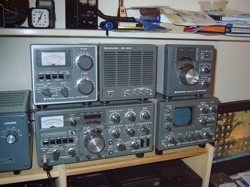
Of course, once I had the TS-820 up and running, I had well and truly caught the boat anchor bug, and then proceeded to set up up a complete station of contemporary accessories from the TS-820 era. Referring to the above photo, the station consists of:
TS-820 Transceiver with display option
AT-200 Tuner
VFO-820,Remote VFO
SP-820 Speaker
SM-220 Station Monitor
Original Hand and desk microphones
The boat anchor station performs well and I often receive complements regarding the "on air" audio quality of the station.
You can hear me some Tuesday evenings on the Boat Anchor net on 3620KHz at 1000Hrs Zulu (8:00pm EST)
The TS_820 and similar Kenwood Transceivers are known as "hybrids", since most of the circuitry is sold state, while the RF output stage is tube.. Here are some interesting sites, with useful information on older equipment, particularly Kenwood hybrids.
http://www.n6wk.com/kenwood/ Lots of useful information, manuals, etc
http://www.k4eaa.com Kenwood hybrid sales, restoration, and service
http://www.radiodaze.com/ vintage radio stuff
http://www.pbase.com/dl5oaq/ts820line Kenwood TS-820 lineup
http://groups.yahoo.com/group/TS-520_820_530_830/messages Yahoo TS-820 Group
.
Bob VK2ZRM continues the story:
I recently acquired a Kenwood TS-820 transceiver, a venerable old boat anchor (old radio), renowned for robust construction and excellent “on-air audio. This TS-820 is fitted with the digital display option, which became standard on the TS-820S model. This point is relevant to our story. It also had at least one known fault in the AGC area. (More of this in a subsequent article).
Now a few words to set the scene: The Kenwood TS-820 is a “hybrid” transceiver, in that it is solid state in the receiver section and valve in the output section. It is also very modular in construction with separate boards for each section, interconnected via bundles of wires and 0.1” pitch pins and sockets. This makes the transceiver relatively easy to trouble shoot, but brings with it the problem of bad pin connections. Cold solder joints on the PCB’s are also a known issue.
Attached to the rear of my TS-820 was a small aluminum box. (Picture). Several Hams familiar with the TS-820 commented that this was the DC to DC converter enabling the transceiver to be used mobile. ( as an aside- the weight of the TS-820 would surely rip the dashboard off a modern car. They don’t make ‘em like they used to!). Being the curious type, I naturally had to have a look at what a DC to DC converter looked like.

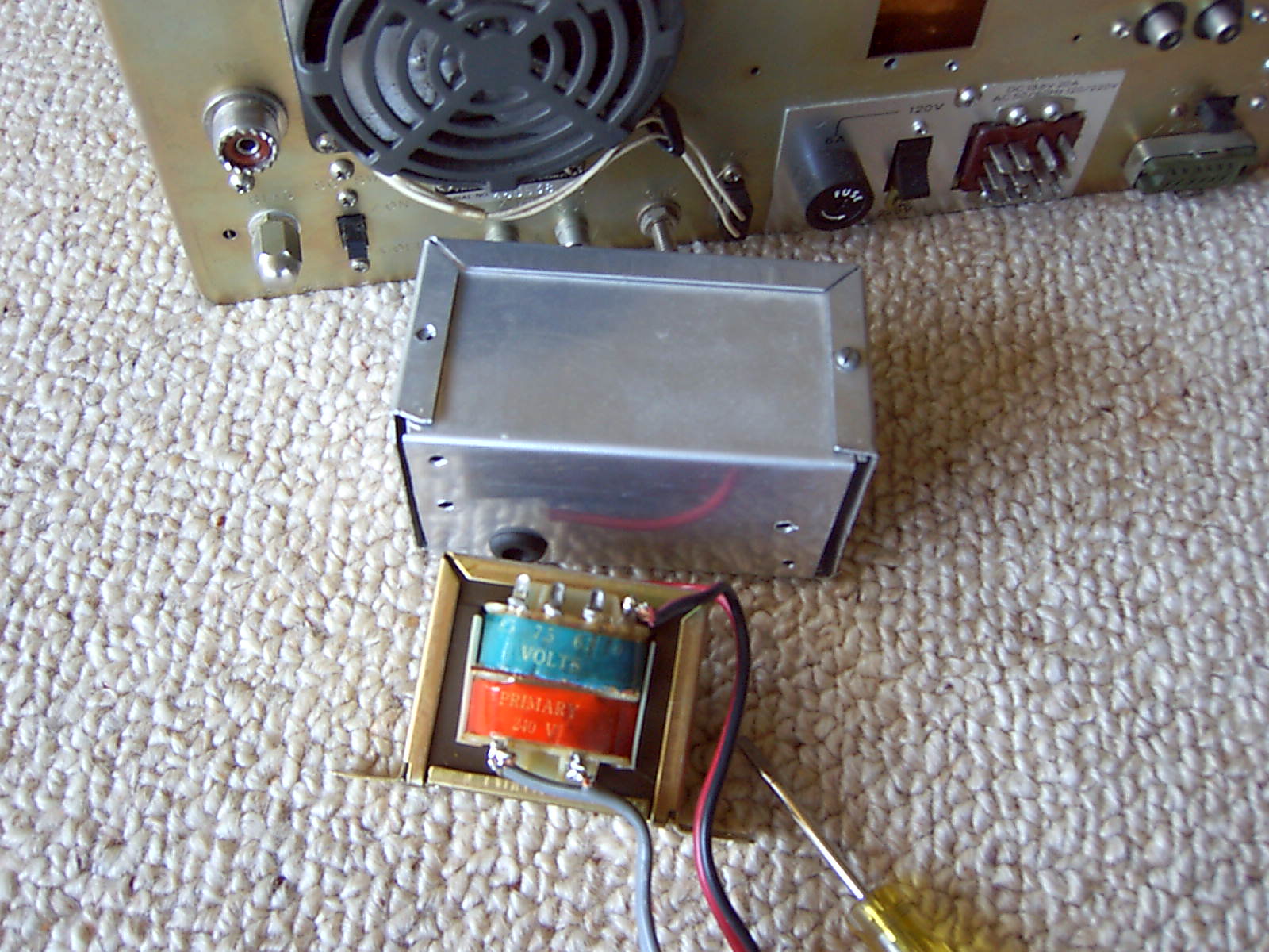
To my surprise the metal box contained not a DC to DC converter, but rather a small ac transformer. (Picture). Following the output leads of the transformer, I discovered they led to a makeshift low voltage rectifier connected to the 5 volt regulator powering the optional counter display module. Normally this regulator is powered from the main 14 volt rail of the transceiver.
So why the auxiliary power supply? Was the 14 volt rail incapable of powering the counter display module? Was there a problem with TTL switching noise getting out of the counter display module back into the transceiver?
I joined the Yahoo TS-520/820 group and posted a question about the problem. I got a reply in no time advising me that there were no issues with the basic transceiver and it is perfectly capable of powering the counter display module from the 14 volt rail. Tin way of explanation: the raw 14 volt rail is generated via a winding on the main transformer and four rectifier diodes on the main rectifier board. This rail should measure approximately 14.5 volts. This rail then goes through an inductor (choke) to provide further smoothing and regulation and drops to approximately 13.5 volts and is distributed to the low voltage sections of the transceiver.
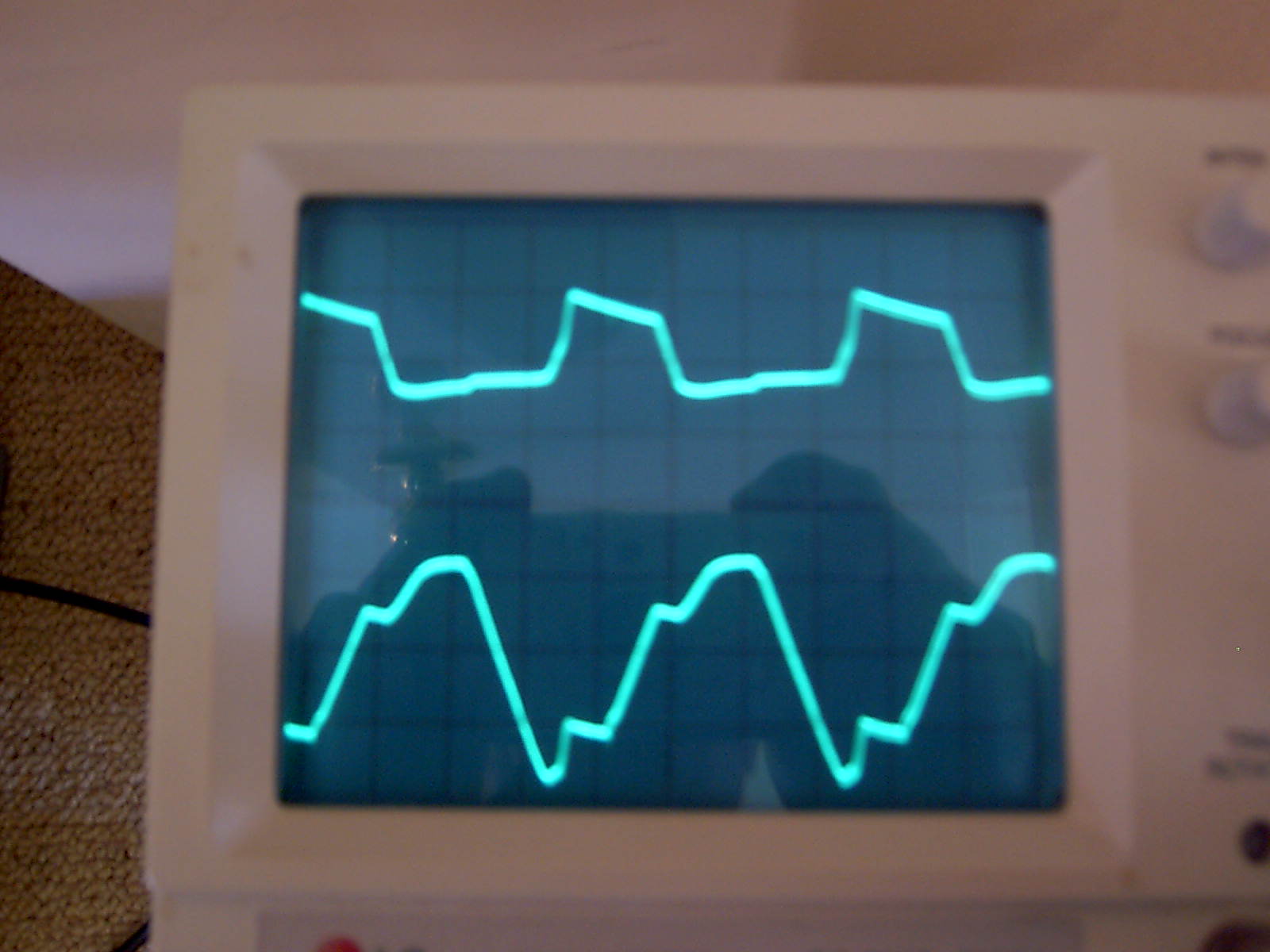
On my TS-820, the raw 14 volt rail measured around 13 volts and dropped to under 12 volts after the choke. Something was wrong. A check around the 14 volt rectifier with a multi-meter did not show up any obvious problems, but monitoring the two ac inputs to the rectifier with my oscilloscope showed an imbalance between the two inputs. (Picture). Examining the rectifier diodes with a magnifying glass showed one of the diodes was cracked. The problem then was that only one half of the rectifier was working, hence only one half of the energy was being delivered to the 14 volt rail.
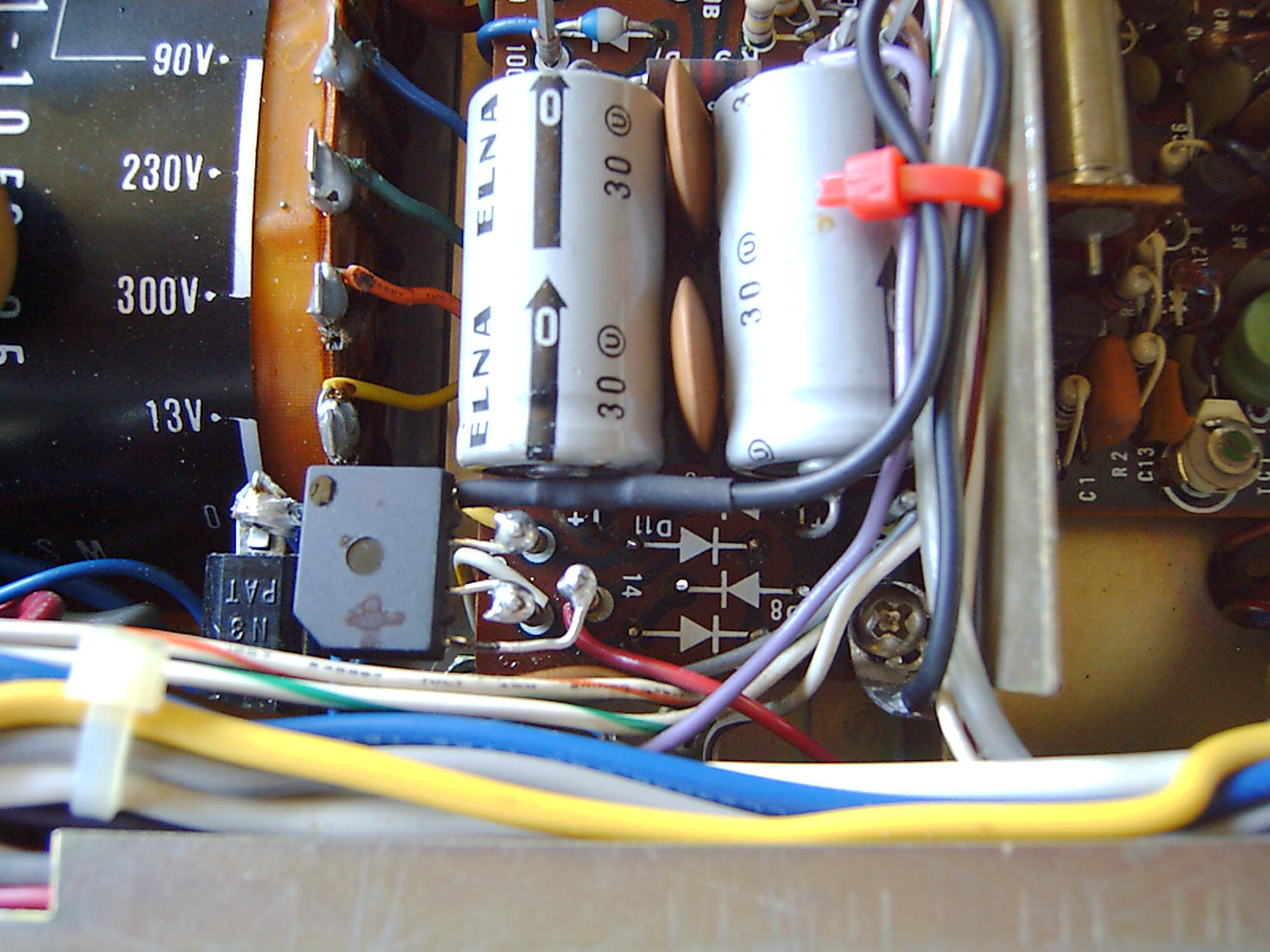
Now for some reason known only to the designers of the TS-820, the connections to the rectifier board are wire wrapped rather than soldered and as there are a large number of connections to and from this board, I felt that trying to access the underside of the rectifier board may cause more problems than I would solve. So instead, I clipped the rectifier diodes off the top of the board and fitted a small bridge rectifier in their place. (Picture). I then removed the “mysterious tin box” and restored the correct connections to the 5 volt regulator supplying the counter display module.
Problem solved. But why go to the trouble of fitting an auxiliary power supply, rather than get to the bottom of a relatively simple problem, and fix it properly?
Who knows? Anyway, it was an interesting exercise and helped me become familiar with the old brute.
They say you should try and learn something new every day. I have certainly leant a few things via this old TS-820. I've spent countless hours on the thing and had lots of fun mixed with frustration.
You have probably already read about the "Mystery of the tin box", on the rear of the 820. I recently fixed an AGC problem, which was apparent when I first acquired the TS-820 from my radio club.
The problem exhibited itself at start up, with the "S" meter pegging right over at maximum deflection, with no audio signal available. Apparently, the AGC was full-on and completely shut the receiver down. After some time, the needle would gradually fall back to zero.
On the Yahoo TS-820 group and there were several references to this AGC problem occurring in humid weather, so I thought maybe it was caused by gunk on the PCB absorbing moisture. The problem on my TS-820 was worse in wet and cool weather,.
I removed the IF board and went to Jaycar ( a local electronics shop) and bought a can of Circuit Board Cleaner and gave the back of the PCB a thorough clean and blast with the compressed air.
I then assembled the plugs onto the IF board incorrectly and was sure I had blown the thing up. But no, when I fitted the plugs correctly, the 820 burst into life.
It seems now that I have fixed the intermittent AGC problem. Fingers crossed.
I think what was happening is that current (voltage?) was leaking into the base of Q16, the agc amplifier and turning it on, thus pulling the AGC line down and shutting down the receiver. Either that, or the the AGC line was leaking to ground, or perhaps a dirty pin, or perhaps..................
Q16 the AGC transistor seemed to be conducting, even without an input signal, but it's very hard to measure the AGC circuit as the high impedance looking into the digital multimeter had a significant impact on the AGC behaviour.