1. Why Are Vertical Antennas Noisy
2. Two Experimental Helically Wound Vertical Antennas
4. A Multi-band antenna for Restricted Spaces - Based on The VK2ERG Shortened Dipole
Why Are Vertical Antennas Noisy?
During a QSO with an “F” call recently on 40 metres, he commented that he was using a homebrew vertical antenna and had quite a bit of noise at his end. I observed that it is generally accepted that vertical antennas are noisier than horizontal antennas, but I did not know why.
A few evenings later on the HADARC HF net I posed the question as to why vertical antennas seem to pick up more noise than other antennas. Several people offered opinions. John VK2ZOI said that he believed most man-made noise is vertically oriented, but did not understand why this should be so. Peter VK2ZPT thought that it might be related to electric and magnetic lines of force in electromagnetic radiation (radio waves).
The opinions offered seemed plausible, but I was still not satisfied, so I got onto the computer and “Googled” the topic. L. B. Cebik, W4RNL offers the following explanation. I quote Cebik:
“Man-made noise: This category includes the usual machinery sparking, faulty signs, auto engine sparking, etc. As you can see from thinking about the sources, it largely derives from spark generation and hence produces useless RF over a wide frequency range. Most human-made noise is vertically polarised and of ground wave propagation. Hence, ground-mounted verticals are most susceptible to this category of noise. A horizontal antenna generally shows an immediate 3 dB reduction. Additionally, antenna elevation also helps reduce the noise level”.
While the above still does not explain why QRM (Man-made noise) is vertically polarised, it does explain why vertical antennas are more susceptible. In my opinion, the key point is that most vertical antennas are mounted close to ground and often have a system of radials that are laid on or under the ground. The other key point is that QRM is ground wave propagated. Of course Cebik neglects to mention QRM generated by computers, DVD players, Microwave ovens, etc, etc. Also, vertical antennas have a low angle of radiation on transmit and hence also receive low angle signals, which in this case are being radiated by man-made devices, as ground waves.
Owen Duffy, VK1OD (a very knowledgable amateur) offers a contrary explanation. Owen’s opinion is that QRM is both vertically and horizontally polarised and propagated via ground waves. The horizontal content of the wave is more quickly attenuated by the ground, leaving mainly vertical content. (Owen's site is www.vk1od.net )
So, there we have several possible explanations as to why vertical antennas are more susceptible to noise man made noise.
Further discussion is invited.
Now, if you have not already visited L. B. Cebik, W4RNL’s site, you really must do so. This has to be the premier Ham Radio site on the Internet and contains a wealth of information that I will not even attempt to summarise. Find out for yourself at http://www.cebik.com/radio.html
Health Warning:
Amateurs entering the Cebik site, particularly those interested in antennas, may never be seen again.
If you enjoy “messing about with antennas” and you are prepared to improvise a little, you may find this homebrew project interesting.
A few weeks ago I had a contact with Charlie VK3TCV. He had just completed a homebrew helically wound yagi antenna for 40M. I was his first contact. He had a huge signal. Later that night I heard him talking to Pedro NP4A I Peurto Rico. Pedro was complementing Charlie on his big signal.
This got me thinking. I had been researching antennas for restricted spaces for some time and decided to give a helically wound antenna for 20M a go. I got out my trusty ARRL Antenna book, but could find no reference to helically wound antennas. I “Googled” the topic and could find precious little on the topic. I turned up these two sites:
· A Two Dollar Helical HF Portable Antenna – http://aditl.com/ham/helical-antenna/index.html
·
A Three Element Yagi Mini-Beam Using Hamsticks -http://www.telusplanet.net/public/ve6vk/minibeam/minibeam.html
Then Ralph VK2IRP came to my rescue with his copy of the ARRL Antenna book. I had been looking in the wrong place. I should have been looking for “Continuous Loading”, rather than helically wound.
So where to start with my compact, helically wound antenna for 20M? Perhaps I should start with a short vertical and go on from there with a rotatable dipole, perhaps ending up with a two-element beam?
The Antenna Book is a little vague, with statements like “No strict rule has been established concerning how short a helically wound vertical can be before a significant drop in performance is experienced”,
And
“There is no hard and fast formula for determining the amount of wire needed to establish resonance in helical antennas. Experience has indicated that a section of wire approximately one half wavelength long, wound on an insulating form with a linear pitch (equal spacing) will come close to yielded a resonant quarter wavelength”.
Compact Vertical Antenna
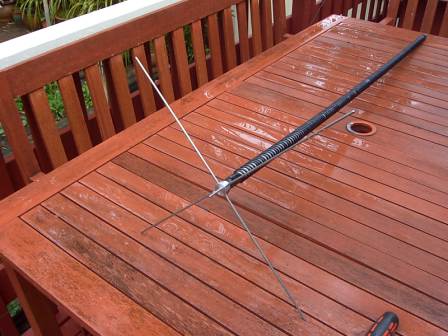
So anyway I decided on an element length of 5ft (Approx 1.5M) of 5/8 inch (16mm) plastic conduit. I fashioned top and bottom mounts and with the help of my teenage son, wound approximately 10M of 2.5mm OD plastic coated wire in spiral fashion on the full length of the former, attaching the ends of the wire electrically to the top and bottom mounts respectively. The bottom mount had a standard 5/16” mobile antenna mount internal thread and the top had a 1/8” hole with grub screw.
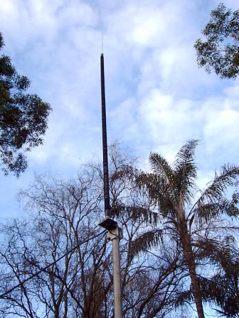
I mounted the newly wound vertical onto a commercial mobile bottom mount on the railing of my back deck and attached two ¼ wave +5% radials or counterpoises to the ground part of the mobile mount. At the top of my 5ft antenna I inserted a straightened metal coathanger just far enough so I could secure it with the grub screw. With the help of an MFJ-259 antenna analyser, I started pruning this “stinger” with side cutters to bring the antenna system into resonance. I ended up with a stinger approximately 600mm long and resonance at 14.200Mhz.
I soon had made contacts with ZL, VK3, VK4 and VK5. Although signals were not as good as with my full size dipole, I was amazed at how good this short antenna was.
To reduce the “Q” and broaden the frequency coverage of the antenna I also tried “top hats” with 4 horizontal radials, each about 250mm long.

Thus encouraged, I decided to take the project to the next step and construct a second identical 5ft whip and use the two whips to construct a rotatable dipole. I made a dipole centre and attached the two whips horizontally opposed.
At this point a problem with my method of construction became apparent. The plastic conduit was too flexible and the two arms of the dipole drooped alarmingly. I fixed this problem by supporting the ends of the dipoles with cord, up to a central point, above the dipole centre.
A “hairpin match” (actually a bent coathanger) across the two dipole feed-points brought the system into resonance.
Initial performance with the dipole mounted low was disappointing, certainly inferior to the vertical. Getting the dipole up high, about in line with the roof ridgeline improved things dramatically. I was soon making contacts with ZL and even broke through a pile-up with VK0AG at Davis Base in the Antarctic. He gave me a 5/9. Not bad for a 20M dipole with only a 10ft wingspan!
The next logical step would be to construct two more elements and make a two element Yagi Beam. This will have to wait till I locate suitable material for the formers, as despite much research I have not been able to locate suitable material at a manageable cost.
Well I hope you found this article of interest and maybe even inspire you to give it a go.
Happy homebrewing.
VK2ABQ Mini-Beam – A compact Beam Antenna That Can Be Built At Home
Now I hasten to add that the terms "compact" and "mini" are relative terms. Even at approximately half the size of a full sized 20M beam, this is still an imposing antenna – in my backyard at least.
Introduction
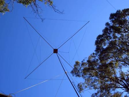
A member of the VK2ABQ "family" of compact antennas, this design is based on a lightweight, wooden "X" frame with two folded and linear loaded wire elements. The two elements are approximately a half-wave each. The front element is broken in the middle and driven via coax. This then is the "driven" element and the rear element then becomes the "reflector".
The antenna is directional and must be turned to face the station you are contacting. Mounted on a mast, the whole structure can be rotated via a rotator, or via the "armstrong" method, (by hand).
Fred Canton – VK2ABQ (Silent Key)
Fred Caton immigrated to Australia some 40 years ago and set up house in the western Sydney suburb of Merrylands. Over the years Fred developed and published a number of designs for compact beam antennas. Originally published in Electronics Australia magazine in the 70’s, subsequent variants were published in the RSGB monthly magazine "Radio Communication". Fred published multi-band and mono-band designs. This is a mono-band design and can be scaled for the required band.
The VK2ABQ antennas remain one of the few designs that are within the capabilities of most homebrewers, requiring no special tools or skills. Basic woodworking tools, such as drill, saw and screwdriver is all that is required. Materials can be purchased at your favourite hardware and electronics store.
Construction Details for the 20M (14Mhz) Version
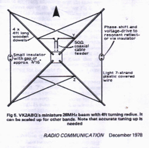
Referring to the diagram and the photograph, you will see that the antenna is built on a lightweight frame of non-conductive materials, in an "X" configuration. I used four, 2.4 metre, 16mm wooden dowels, screwed to a centreboard made of thick plywood. An attachment point on the underside of the plywood centrepiece enables the assembly to be mounted on a light mast. To counter the "droop" in the dowels, I used a vertical dowel on the centre board with light ropes supporting the ends of the 2.4M dowels.
The diagram actually shows a 10M (28Mhz) antenna. I scaled this up by doubling all dimensions. The 2.4M dowels are actually a little short so I extended them with a 150mm length of electrical conduit on the outer ends of each of the dowels. The points marked "Y" and "Z" on the diagram are halfway along the length of the dowel (about 1.7M). The wire used is medium plastic covered hookup wire. There is a small gap of about 4 to 5mm between the ends of the elements.
The starting point for the total length of wire in the antenna is approximately 21.3 metres (75ft), divided equally between the two elements. The small gaps between the front and back elements are exactly in the middle of each side.
Tuning is a little tricky as the point of resonance increases in frequency with height, so you must "guess" at what frequency to resonate the antenna on the ground, so it will be correct once it is up the mast. About 300 to 500Khz seems about right. An antenna analyser is an invaluable tool during this process.
Front to back ratio does not seem to be all that good, but some additional tuning might help. I may try shortening the driven element and lengthening the director. There are deep "null’s" off the sides though.
Conclusion
Well there you have it. This antenna should be within the capabilities of most homebrewers. No special tools are required. My total cost was under $30 as I used scrap material and wire I had hanging around. Dowels, metal mounting brackets etc all came from Bunnings.
Happy homebrewing. Bob VK2ZRM
A MULTI-BAND HF ANTENNA FOR RESTRICTED SPACES, COVERING 80, 40, 20 and 15M - Based on the VK2ERG Shortened 80M dipole
Many of us city dwellers have limited space for putting up HF antennas, particularly full size 80M dipoles etc. For some time I have been looking for a multi-band antenna system that will enable me to join the HADARC 80M Wednesday night HF net, with adequate signal strength, while at the same time providing excellent performance on 40M and 20M (and on other bands if I desire). Recently a member of our own club, Earnest VK2ERG (formerly VK2ADW) provided the catalyst for the antenna system I outline here.
Referring to Figure 1. the antenna system is based on a “half-size” 80M dipole, shortened via loading coils in each leg. Other bands are covered by full-sized half wave dipoles, fed from the same feed point as the 80M dipole. I chose to cover 80M, 40M and 20M with my antenna system. Other bands could have been chosen and the dipoles cut to cover the required band(s). As an added bonus, the antenna also covers 15M, as well.
I call it an “antenna system” as the dipoles, Balun, feed line, and ATU (Antenna Tuning Unit) all form an integral unit, or system. The shortened 80M dipole is 20 metres end-to-end and fits nicely across my backyard. The 40M and 20M dipoles are separated by about 30 degrees from each other, and are arranged as “inverted V’ees”. The 15M band is covered by using the 40M dipole and the ATU.
The system performs well and subjectively, the 80M dipole is less than one “S” point down on transmit, compared to a full sized antenna, although of course the radiation pattern may not be ideal. Its performance on receive is excellent. The 40M and 20M dipoles being full size perform very well indeed, and I regularly get 5 by 9 +10 or +20 reports when running barefoot, both locally and into ZL. Performance on 15M is good as well.
One down side of any shortened antenna is reduced bandwidth, hence the use of the ATU on 80M. The ATU is optional on the other bands. If you like to “rag chew” up and down the 80M band, then this may not be the antenna for you. If however you are happy with a compromise on 80M and excellent performance on other bands, then give this antenna a try.
Now For the Technical Stuff.
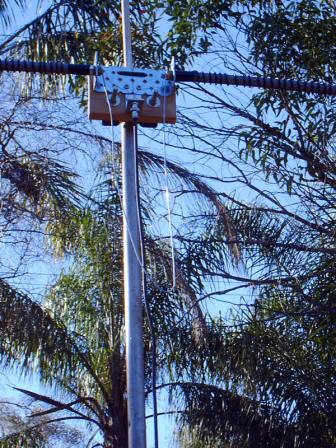
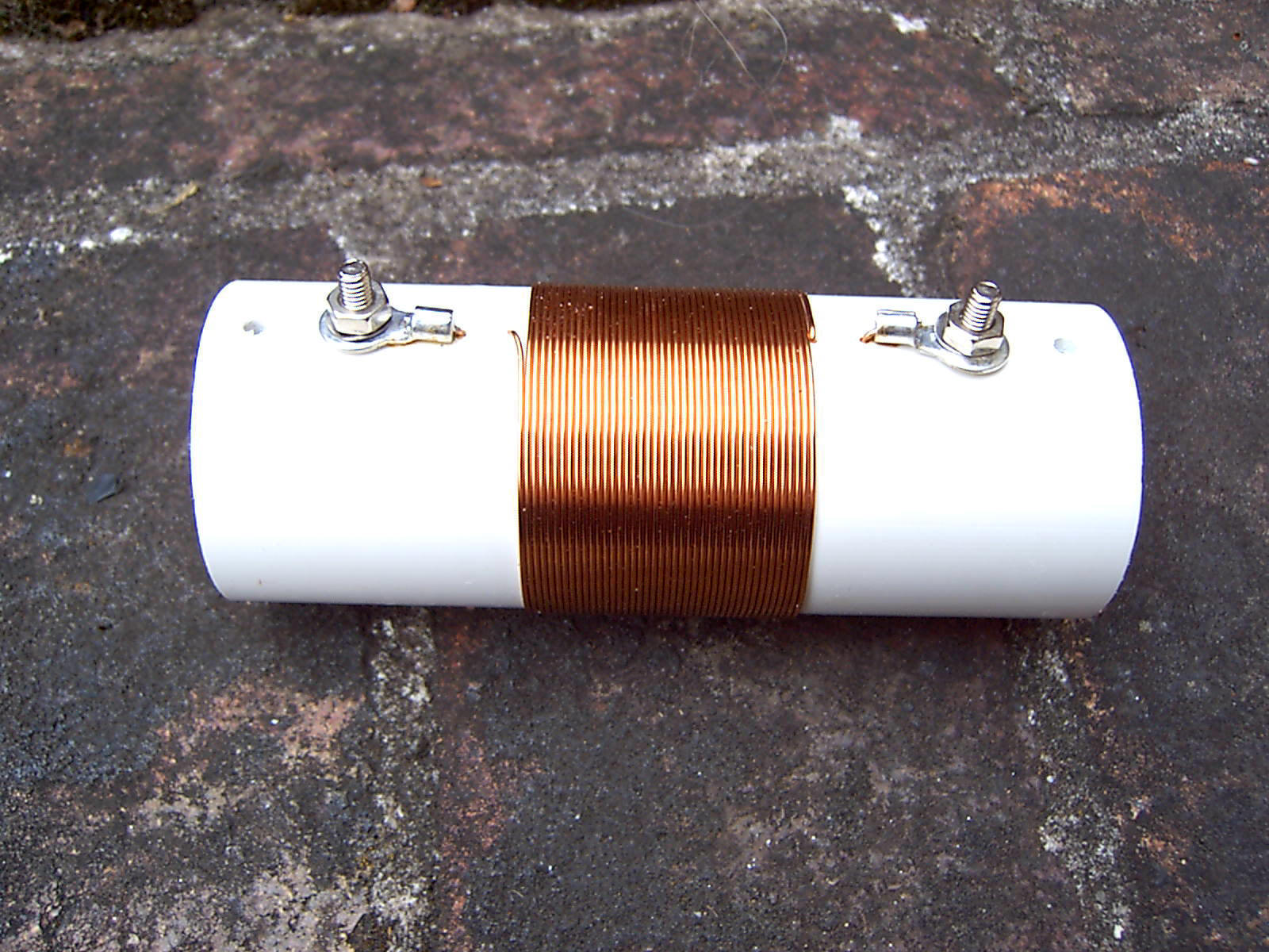
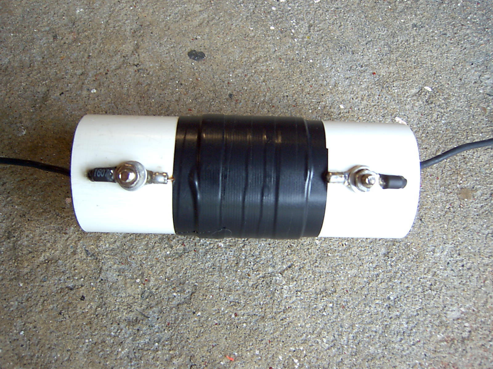
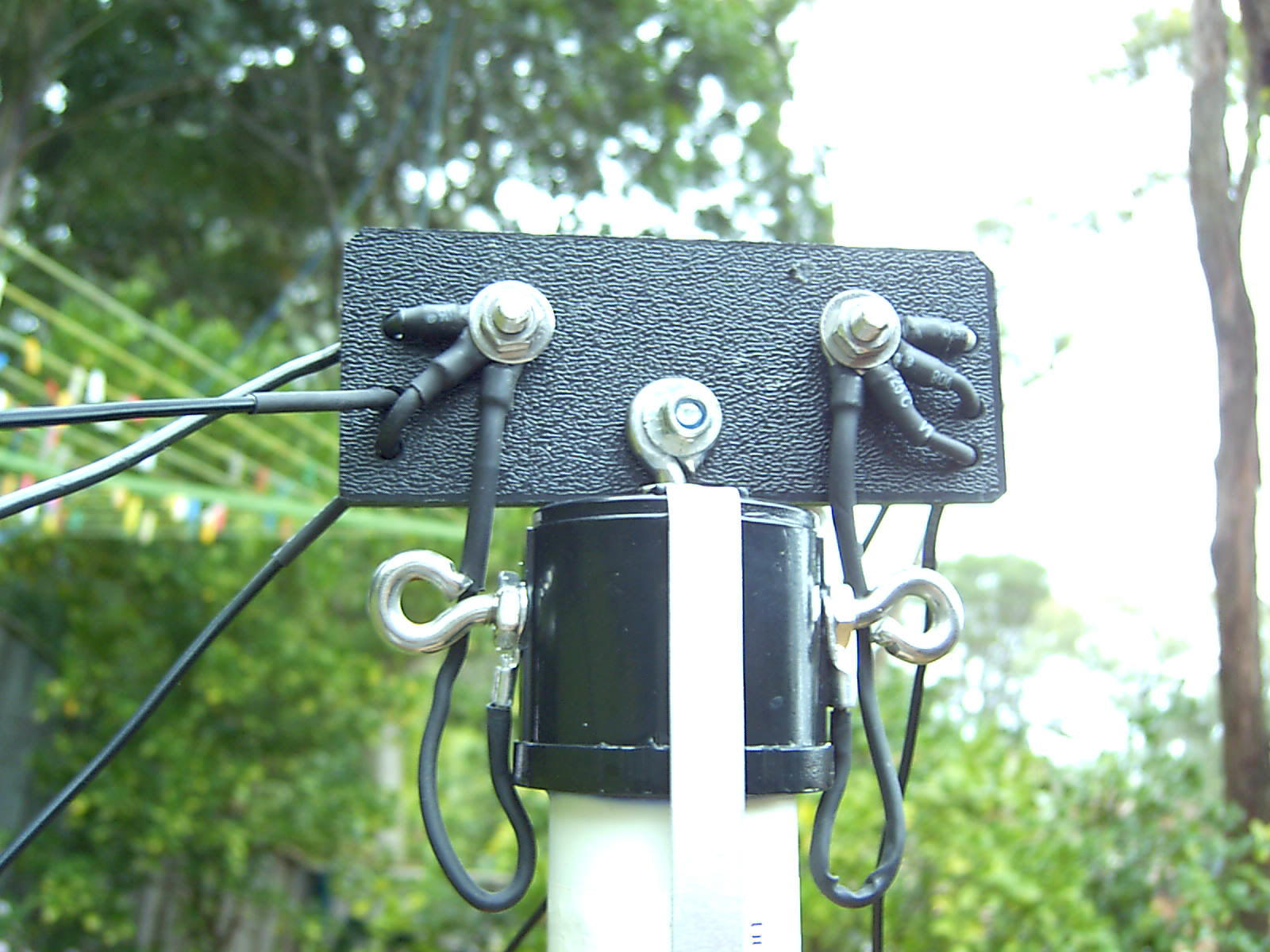
As shown in Figure 1. the inside leg of each of the 80M dipoles is 6.1 metres long, the outside leg being 3.9 metres long. The coils are identical and are wound using 0.8mm enamel covered copper wire. The coils are 42 turns, close wound on lengths of white plastic sewer pipe. The inductance of each coil is about 54uH. A 1:1 Balun is at the feed point and the antenna is fed with 50 Ohm coax, from the ATU. The photos show the construction method I used.
The ATU is necessary due to the narrow nature of the shortened 80M dipole and also because the best SWR I was able to obtain was about 2.3:1 on 80M. The SWR is around 1.2:1 on 40M and 20M. The ATU also facilitates using the antenna for 15M as well.
Now, although 2.3:1 SWR on 80M sounds high, do the maths. Go to the Internet and find a coaxial cable loss calculator. Owen Duffy VK1OD has and excellent site which includes a number of calculators. (http://vk1od.net/tl/tllc.php)
I calculate that at 2.3:1 SWR using RG58, with a feedline about 20 metres long, I lose about 0.75db which gives an overall efficiency of about 85%. Not bad for a half size antenna. Of course the loss on other bands will be minimal, due to the low SWR. If we accept that an “S” unit is equal to 6db then you will see that the loss of 0.75db will be barely detectable at the receiving end, compared to a full sized 80M antenna that is.
Lengths for the full size half wave dipoles are calculated using the standard formulas from the antenna text books and the site below.
This site has lots of useful stuff, including information and calculators for designing antennas. www.K7mem.150m.com
Here is another 80M half size dipole project.
http://www.qsl.net/vk3jeg/loadpole.html
Happy Homebrewing – VK2ZRM